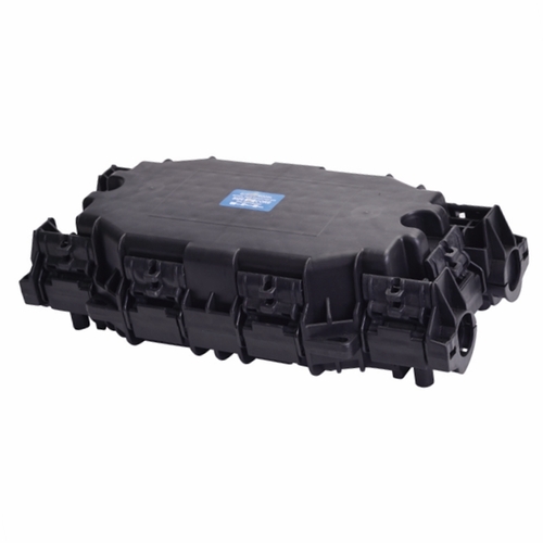
Fiber Optic Splice Closure Role Classification Installation Requirements
Fiber Optic Splice Closure is used for fiber optic cable connection protection. It can be used in optical cable lines for overhead, direct burial and pipeline laying.
First, the classification of the optical cable connector box:
1. According to the shape, it can be divided into horizontal and vertical.
2. According to the fiber optic cable connection, it can be divided into the straight-through type and divergent type.
3. According to whether the adapter classification can be assembled, it can be divided into an adaptable adapter type and a non-assemblable adapter type.
4. According to the material of the outer casing, it can be divided into the plastic casing and metal casing.
Second, the optical cable connector box installation requirements:
1, fiber preparation
Remove the outer skin of the cable, and then remove the surrounding layers to expose the loose tube. For the specific method, please follow the standard method recommended by the cable manufacturer, and the reserved length is 3m. Clean the loose tube and the core-sheath with a cleaning agent, remove the excess filling sleeve, and use the supplied sand to polish the cable outer paper 150 mm long.
2, the installation of optical cable
a. Select the closed loop of the smallest inner diameter according to the outer diameter of the cable, and place the two closed loops on the cable.
b. Place the fiber optic cable into the corresponding access hole.
c. Connect the shield and ground.
d. Wrap a self-adhesive closure tape between the two seal rings so that the seal band is wound flush with the outer diameter of the closure ring to form a closed end of the cable.
e. Press the cable end of the cable into the hole of the cable.
f. Use the hose clamp to pass through the cable and the cable holder, fix the cable to the base of the connector box, and rotate the hose clamp until the hose clamp is tightened.
g. Put a green nylon cable tie on the outgoing cable and cut off the excess length; tie the blue nylon belt on the user cable and cut the excess length.
h. The remaining unused cable holes should be sealed with a plug. The sealing tape is also wound on the plug. The requirements are the same as in 5.2.4.
i. Wrap the reinforcing member around the countersunk screw of the splice tray holder and press it.
3, fiber connection
An optical fiber coiled 1.5 turns behind the disk is reserved, and then the remaining fibers are all wound around the casing. Use a single-core buffer tube for the single-core fiber tray and a ribbon buffer tube for the ribbon-shaped fiber tray. Nail with a nylon cable tie at the entrance of the splice tray. Use a different color nylon cable tie to separate the office cable and the user cable. Dock two (belly) fibers according to the specified method. The connector is snapped into the slot of the fusion unit. The excess length should be coiled in the disk. Cover the splice tray and gently press it into place.
According to the different capacity required of the joint box, the number of superimposed discs is determined. The superimposed form of the splice tray must conform to the snap-in welding unit of the fiber optic connector and the inspection and maintenance requirements.
4, the box seal
Box Encapsulation Close the valve tip to the grounding screw before encapsulating the case. Insert the sealing rope into the sealing groove around the box; also insert the sealing rope into the groove at the "U" groove at both ends of the joint box. Note: Use a sealing rope and do not artificially stretch the sealing rope to avoid leakage.
Gently close the top cover of the joint box and screw in the fastening bolts. The tightening sequence is tightened according to the numerical order indicated on the cover and tightened with a torque wrench. The torque is 25Nm. After five minutes, tighten with a torque wrench and the torque is still 25Nm.
5, the removal of the lid
Loosen the 10 fastening bolts in sequence, and the cover and seat are still together. Take four fastening bolts into the four corners of the box, and rotate them symmetrically and evenly into the four-corner top cover to separate the cover and the seat up to 6mm. After 5 minutes, the lid is separated from the seat by more than 6 mm in a uniform top cover until the lid and seat can be easily separated by hand. Note: The cover must be gently removed during separation to avoid damage to the fused fiber.
If the capacity is increased or the inspection is completed, the cover must be reassembled. The old seal rope must be removed and the sealing rope must be re-applied to the seal groove, including the seal at the inlet port of the “U” slot cable.
Recommended Products
-

Boltless Inline FOSC GJS-H020
Fiber optic closure is a passive component which can provide...
-

Fiber Optical Pedestal FOP-16B
FOP-16B fiber optical pedestal is designed specifically for ...
-

DOME Fiber Optic Splice Closure Empalmes verticales de fibra óptica 288cores GJS-D023
Fiber optic closure is a passive component which can provide...
-

Cajas Terminales ópticas para interior de edificios CTO-32E
CTO-32E is an optic distribution box for FTTH application wi...
-

Network Access Point NAP box FATM-0416AT
FATM-0416AT fiber access termination box is able to hold up ...
-

Optical rosettes Fiber Rosette FRB-1J
FRB-1J fiber rosette box is able to hold up to 1 subscribers...
-

OTDR-HJ2100 Series
The worldwide spread of broadband service has stimulated the...
-

Fiber Access Terminal Cajas de Distribucion box FSP-0316A
FSP-0316A fiber access termination box is able to hold up to...
-

Intermediate Optical Distribution Box 9 Cores---IODB-0309A
IODB-0309A box is able to allow the interconnections of the ...

 English
  中文简体
中文简体