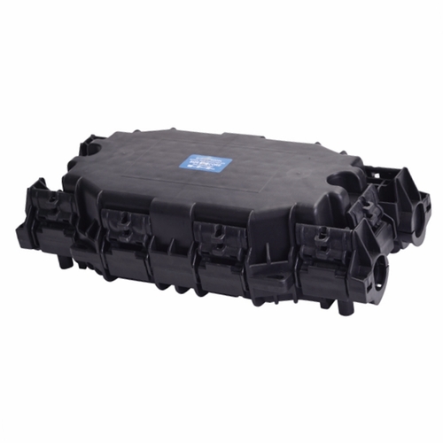
Fiber Optic Splice Closure Installation Steps
Today Green Telecom shares the installation steps for the fiber optic connector.
1. Components in the closure
Fiber Optic Splice Closure kit usually includes: end plate, splice tray organizer, fiber splice tray, cover, cable grommets, grommet retainer, mounting bracket and misc. hardware.
2. Fiber Cable Sheath Preparation
2-1 Expose the rip cord. This step involves mark the location with a tape marker, ring-cut the outer jacket with a sharp knife, remove the corrugated armor if applicable, and shave off the outer jacket to expose the rip cord.
2-2 Remove the outer sheath. This step involves make a longitudinal slit down the outer sheath, peel off the outer jacket and corrugated metal, can cut the rip cord flush with the end of the corrugated metal.
2-3 Remove the inner jacket. This step involves using the rip cord under the inner jacket to slit it, cut aramid yarns, cut central strength member, and clean the filling compound.
3. Bonding and Grounding Hardware Installation
Bond clamp installation. This step involves slide the cable clamp over sheath, slide the bond shoe under the corrugated metal, place the bond plate over the bond shoe and secure the sheath grip.
4. Assembly of Cables to Splice Closure
The preferable location for the two main cables is in the lower end plate port. If a third or fourth cable is required, it is easier to install it in the upper end plate port as a branch cable. This fiber optic splice closure is designed for two cables in each of its two ports. If only one cable will be installed in a port, the provided rubber grommet plug is used to substitute for the second cable.
4-1 Install Cables to End Plate. This step involves unscrew knob and remove grommet retainer, position the end plate assembly, attach the sheath grip to dielectric cables, slide cables and sheath grip through, and secure sheath grip to backbone.
4-2 Grommet Installation and External Grounding. This step involves apply B-sealant, push the grommets into the end plate port, and apply more B-Sealant.
4-3 Fiber Unit Preparation and Distribution Organizer Installation. This step involves remove more loose tubes, separate each cable's loose tube into two groups, position the distribution organizer, secure the loose tubes to the distribution organizer, and secure the loose tubes.
4-4 Splice Tray Installation. This step involves place the splice tray, fasten the end of the splice tray to the organizer, and install cables, grommets and external ground.
4-5 Optical Fiber Splicing. This step involves splice holder placing, fiber splicing and fasten the splice holder lid.
5. Fiber Optic Splice Closure Cover Installation
6. Closure Mounting
7. Reentry
Recommended Products
-

Boltless Inline FOSC GJS-H020
Fiber optic closure is a passive component which can provide...
-

Fiber Optical Pedestal FOP-16B
FOP-16B fiber optical pedestal is designed specifically for ...
-

DOME Fiber Optic Splice Closure Empalmes verticales de fibra óptica 288cores GJS-D023
Fiber optic closure is a passive component which can provide...
-

Cajas Terminales ópticas para interior de edificios CTO-32E
CTO-32E is an optic distribution box for FTTH application wi...
-

Network Access Point NAP box FATM-0416AT
FATM-0416AT fiber access termination box is able to hold up ...
-

Optical rosettes Fiber Rosette FRB-1J
FRB-1J fiber rosette box is able to hold up to 1 subscribers...
-

OTDR-HJ2100 Series
The worldwide spread of broadband service has stimulated the...
-

Fiber Access Terminal Cajas de Distribucion box FSP-0316A
FSP-0316A fiber access termination box is able to hold up to...
-

Intermediate Optical Distribution Box 9 Cores---IODB-0309A
IODB-0309A box is able to allow the interconnections of the ...

 English
  中文简体
中文简体